
| Summary |
Contents |
| · The ammeter shows the amount of current
flow to, or from, the battery. Recognizing when the ammeter is showing normal as opposed to problem conditions is critical. If the ammeter stays far to either side there is a problem. High current can overheat wires and connections. The result can be melted wires or even a fire. Only in extreme situations should the fusible link, if present, fail first. · Many 1960s and 70s Chrysler ammeters were labled 'alternator' on the gage face which can be a little confusing. Think of it this way: If the battery is discharging under normal driving conditions, something is wrong in the alternator circuit. |
Charge
Wire Diagram; Alternator to Battery Charge System Operations - Run when battery is charged - Run when battery is slightly discharged - Start Problems Solutions Complete Charging System Wiring Diagrams page 2: How Fusible Links Work in Charging Systems with Ammeter |
Ammeter needle moves in response to
electrical flow. In the most common automotive ammeters,
the needle is deflected by the small magnetic forces created
when current flows through the meter. These meters are
placed directly in the flow path being measured. Some cars
received externally shunted ammeters. They indicate the same
information, but are wired in differently.
Automotive ammeters are wired to show the battery is
discharging, charging, or neither.
Cars and trucks have two power sources, the battery and the
alternator. The output wires for the battery and
alternator is joined to the wires feeding the key switch, the
headlights, and fuse box at a one or more junctions. On
vehicles with an inline ammeter, this junction is usually a
welded splice under the dash.
When a car battery supplies power, by common convention we say
electricity flows out from the positive post at 12 volts.
The current eventually flow to ground and up the battery
negative cable. When a battery is getting charged,
electricity flows into the positive post.
Electricity always flows from the highest voltage power
source. For a battery to be recharged, it must be supplied
power at a higher voltage. An alternator generates power
at 13.9 to14.9 Volts. Therefore it is capable of
recharging a '12 volt' battery
While the alternator-battery circuit is often called the charge
circuit, its more than that. It supplies power for everything
but the starter. Power will come from either the battery
or the alternator.
Notice the main junction is located between the
alternator and the ammeter.
When the engine is running, no current from the alternator flows
through the ammeter except to recharge the battery.
The output wire from the battery also serves as its charging
wire. All ofthe wires connected to the battery are always
hot!
To protect against an accidental grounding of the battery a fusible link
was placed in the output wire (after 1964).
.
The battery may supply over a 100 amps for several seconds
directly to the starter when the relay closes.
A relatively small amount of current trips the relay and powers
the ignition.

Current from alternator goes to main junction.
Only current for recharging the battery goes through the ammeter.
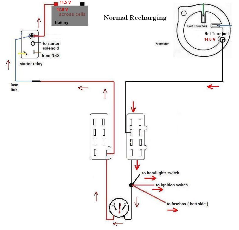
When the battery is fully charged, no power flows
through the charging wires or ammeter.

Connections:
1. Check for oxidation, corrosion, loose connections especially at
bulkhead. Clean, tighten, fix as needed.
2. An
option is to create better connection or directly wire the feeds
through the firewall, either in parallel to, or replacing the
bulkhead connections.
This is essentially the same as Chrysler's modification for
certain fleet use applications and keeps the ammeter.
Another version of this concept was used for later A-bodies
equiped with rear window defroster grids.
3. In theory an option is to rewire the circuit using a remote
shunt ammeter. At least some Chrysler vehicles used a remote
shunt ammeter starting in 1976 as did some other companies (but
not AMC/Jeep). (ref. Rick E. Mopar Action reprinted
at allpar.com) Aircraft supply houses are another
source of remote shunted ammeters/
High Rate of Charging: Maintain battery in good
condition. If battery is low, keep alternator speeds down
and monitor ammeter. Shut off if current is
excessive. Use an alternator that can keep up with expected
power needs at idle. Do not simply use an alternator
that is rated high output, especially if not needed. Output
goes up with rpm, if the extra current is not needed but the
battery is low, it will send all that current into the charging
circuit.
* Photo sequence of low
battery being charged. (posted on For A-Bodies Only).
* More info on alternator
rating games, on Speedtalk forum
Circuits: If adding headlight relays or other high current circuits, draw power directly from the alternator. Add fuse or circuit breaker for each new circuit.
Complete thread by NachoRT74 et al on improving the charging system while keeping the ammeter. (on Dodge Charger forum)
1985 &
1986 AMC Full Size Jeep (SJ) Charge and Headlight Diagrams
(has their own pages)
1967 Plymouth Barracuda:
Typical of alternator systems using positive field regulation
(single field wire at alternator).
Wire colors will vary with year, make, model.
